My household has a problem.
Okay, a minor problem – the main staircase has very poor lighting. There is no ceiling light over the stairs, and they can be quite treacherous as a result, especially overnight. Any sensible person would have thought “let’s just leave a light on in the nearest room at the top/bottom”, and we did as well… But as you can guess by the existence of this blog post, we wanted to do something a little more fun and challenging to pass the time. This is the story of how my roommate Ben and I overengineered a set of motion activated understair lights.
Why?
Well, simply put, because we could.
If you’re interested in learning more about how these lights came to life, check out the rest of this post. If not… well, here’s a couple gifs of the finished product (click on the images to enlarge).
Oh hey, you’re still reading! Thanks!
After some light research we found inspiration in lights like these. They served as a starting point as we decided what exactly we wanted to build.
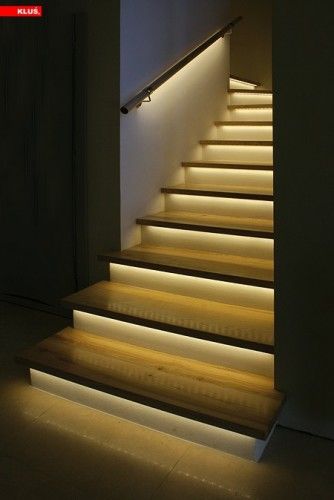
Ultimately, we decided that we wanted to make understair lights that cascade on upwards when one walks up the stairs, and downwards when one walks down. The lights would also cascade off in the same direction after being lit up for a set amount of time. A cooldown delay would be implemented to prevent triggering the lights in the opposite direction if you’re slightly too slow going up/down the stairs – essentially some extra buffer time.
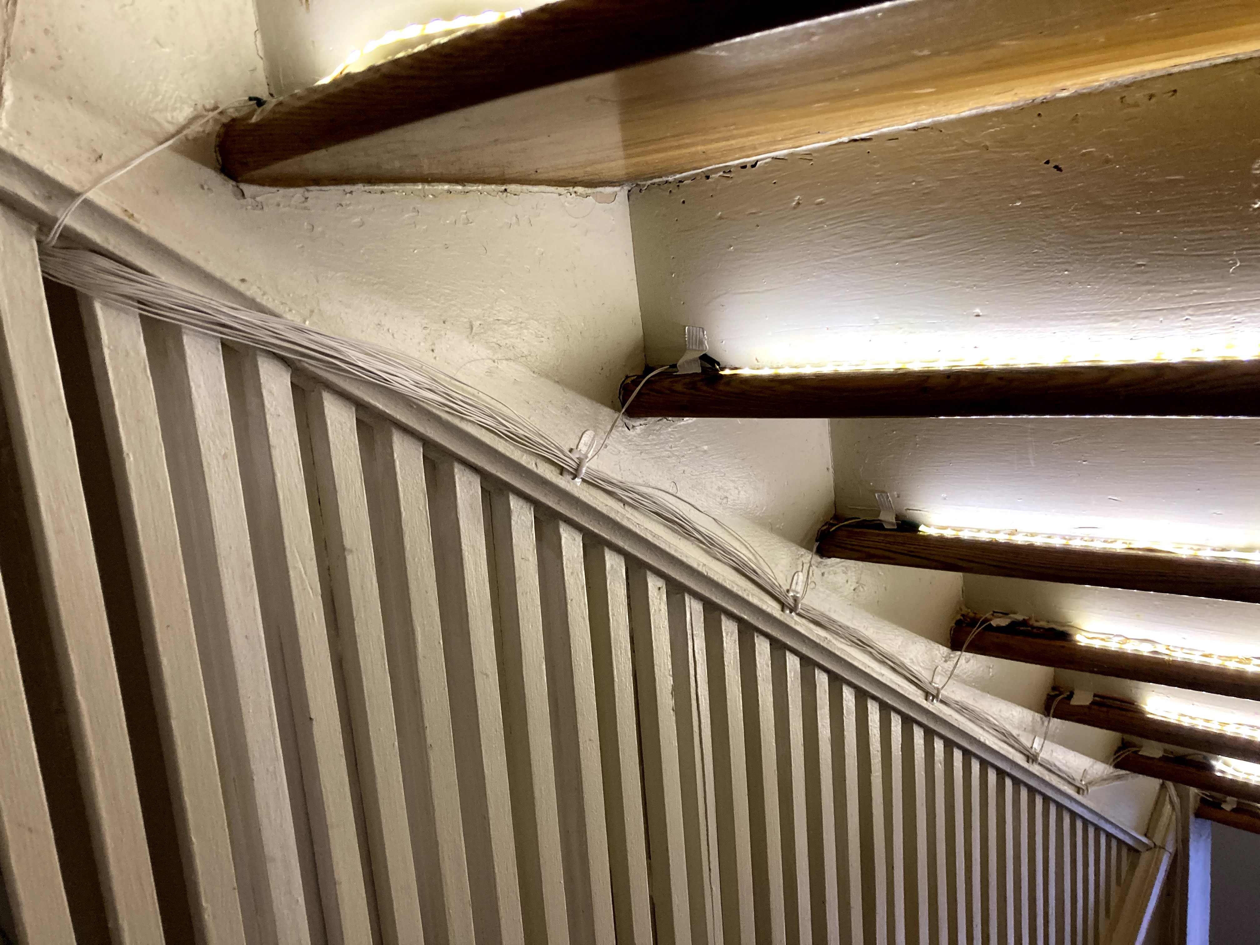
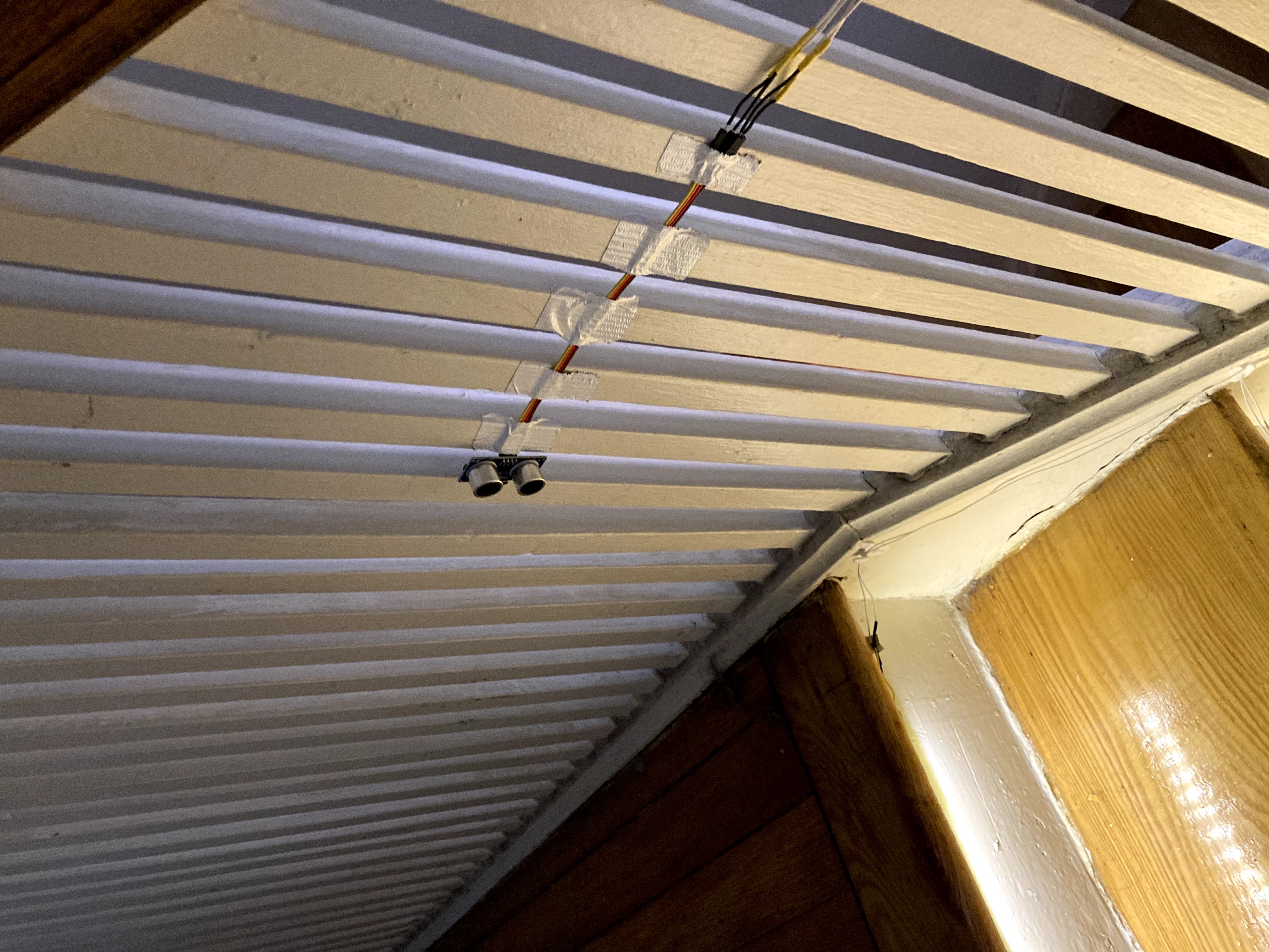
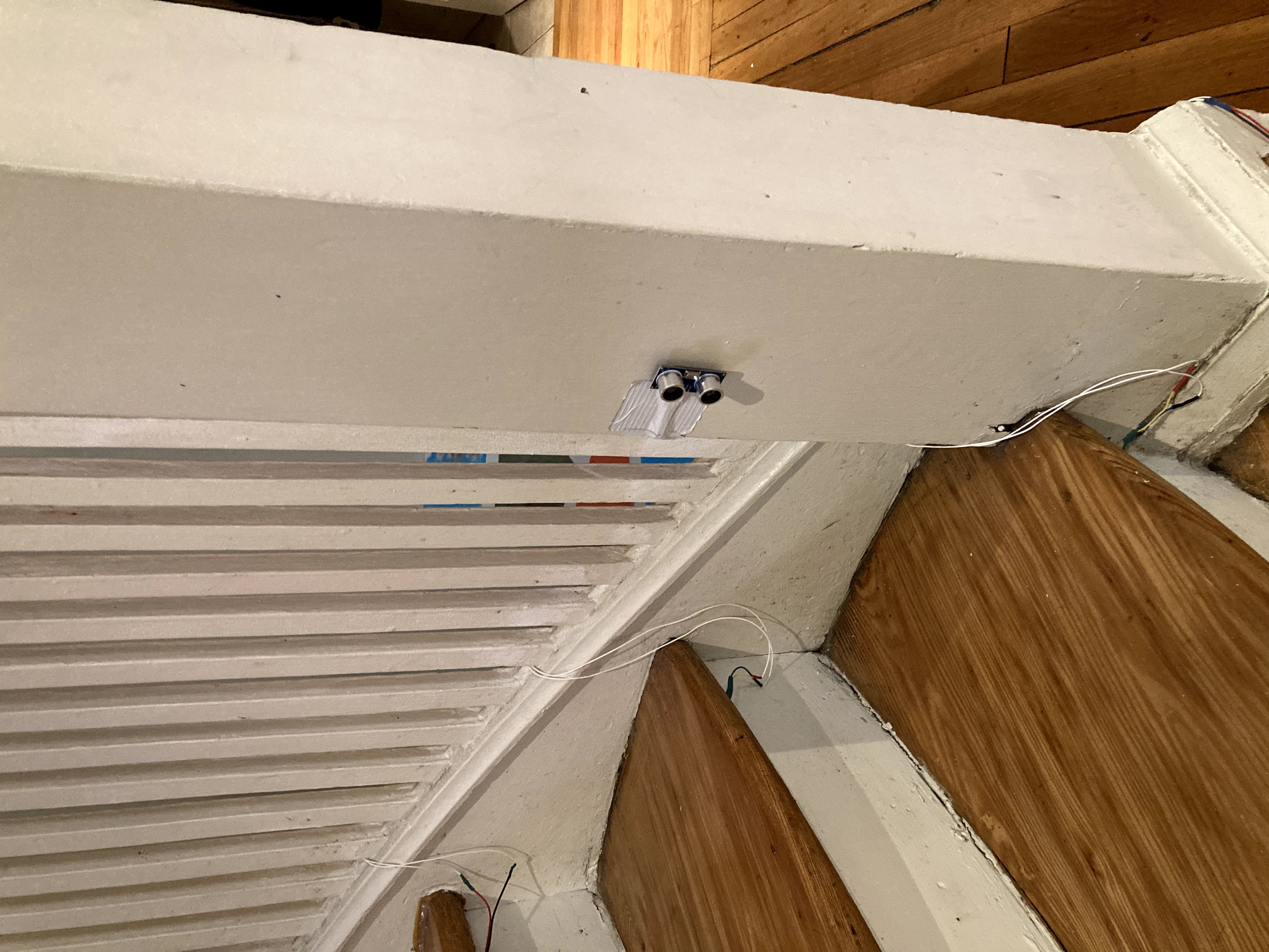
With Ben and myself both having experience with Arduinos in the past, we decided to build on the familiar platform. Each stair would have an LED strip that is connected to a shared power supply. A transistor between each LED strip and the power supply would be controlled by the Arduino and make the lights turn on and off. Ultrasonic sensors would be installed at the top and bottom of the staircase to detect when a person walks by. This would trigger the cascading animations.
Unfortunately, the digital pins required for 16 transistors (there’s four more stairs beyond the landing) and two ultrasonic sensors exceeds the number of pins available on a standard Arduino Uno. As we already had a couple of Arduino Unos lying around, we decided to set up a master-slave system in order to gain access to the additional digital pins.
Well… until one of them tragically died as all electronics eventually do. Then we decided to simplify the whole thing and order an Arduino Mega (with it’s deluge of digital pins), simplifying things greatly.
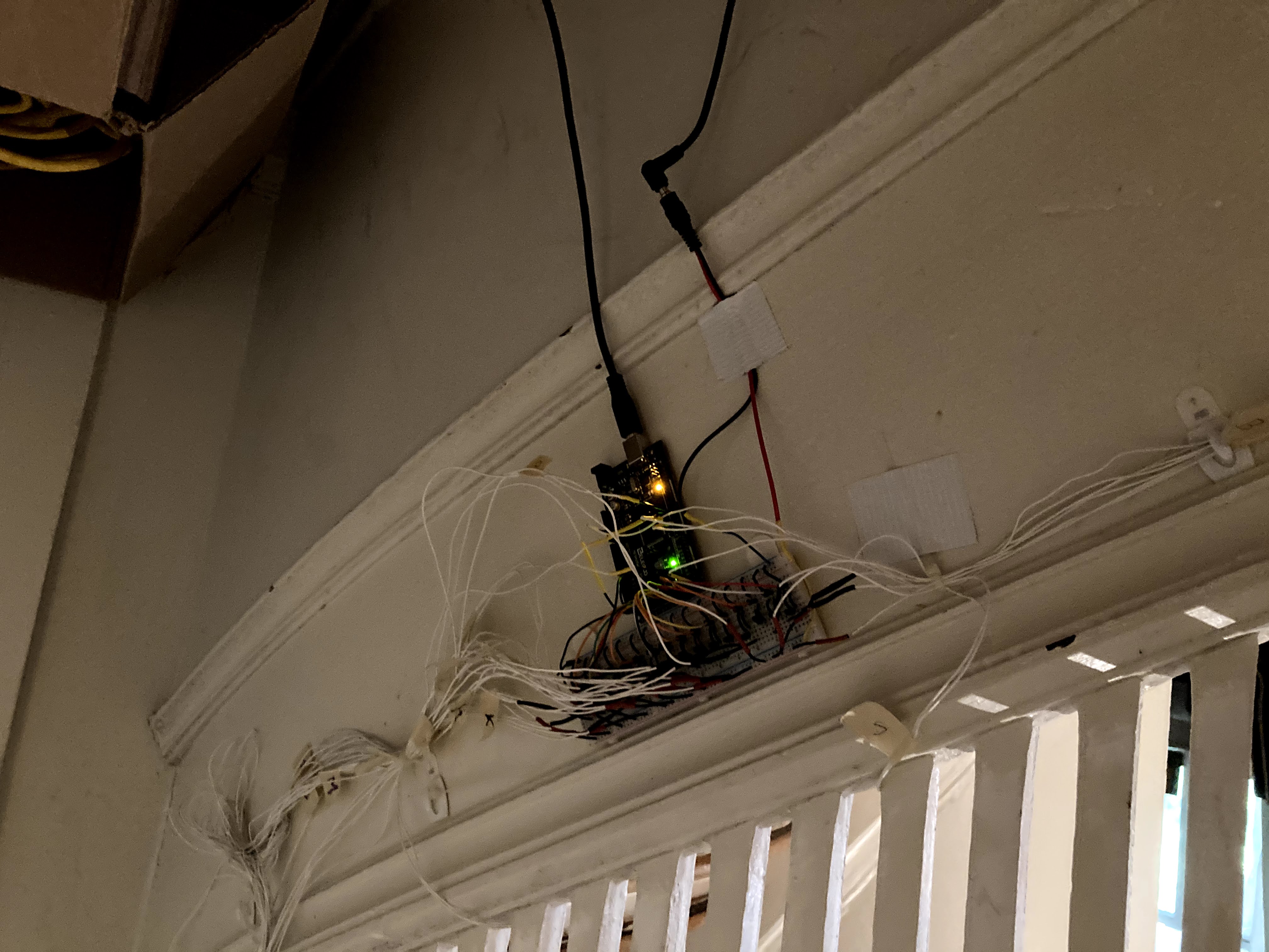
After a couple iterations (and one terrifying spaghetti board that would surely not make it through airport security; see below) we settled on a super simple circuit on a breadboard. Essentially, there exists 16 identical circuits where a transistor acts as a simple “on/off” switch – each connected to a pin on the Arduino. Power cables are run from the breadboard to each stair. The ultrasonic sensors were also connected to the Arduino and placed near the top and bottom of the stairs.
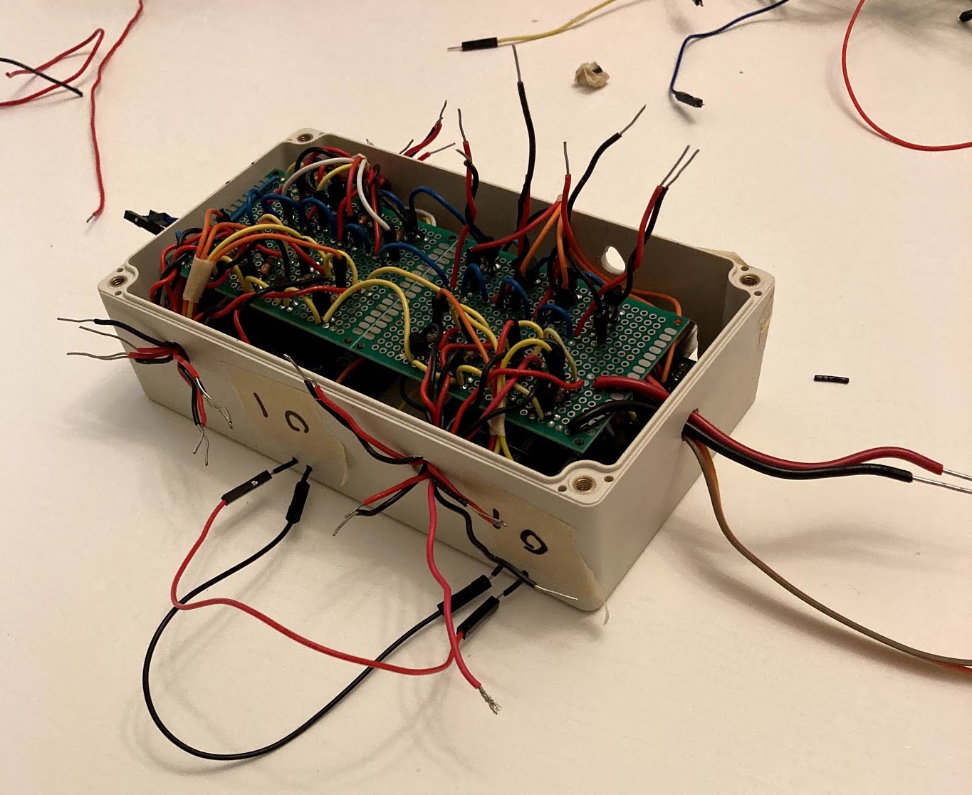
V2 (right). Looks messy, but everything is out of the way, colour coded, and labeled, so it's easy to troubleshoot.
If you’re interested in the code running this build, you can view the repository here. It’s currently set up for our 16 stair configuration, but only requires a few modifications if you’d like to make your own cascading lights. If you have any questions or issues, feel free to reach out to me at stephen@gidge.dev for assistance.
We’re not totally done with this project yet. Up next is brainstorming an enclosure for the main circuit so it’s not living out in the open forever. Following that, our focus will shift to 3D printing a mount for each ultrasonic sensor (well, once the world reopens and we have access to a 3D printer). Duct tape is working fine for now, but we’d rather not rely on it indefinitely. We’d also like to explore implementing a real-time clock to keep a single light on overnight as a night light.
I may publish a follow-up to this article once the last few loose ends of the project get settled. Until then, if you have any questions feel free to shoot me an email. I hope this post gave you some inspiration for your next “home improvement” project! Thanks for reading!
Until next time,
Stephen
Check out Part 2 for a look at how I made these lights react to music real time!
P.S. Here’s one last gif of the lights in action.
LinkedIn Reddit Facebook Twitter